Breadboard Connections
To make programming the PIC convenient, Microchip provides In-Circuit Serial Programming (ICSP). This allows you to program the chip while it is in the application circuit. Without this feature, you would have to remove the microcontroller from the circuit and plug it in to a dedicated programming socket every single time you updated your code. For PIC, ICSP includes the following pins:
- Vpp: Programming voltage.
- Vdd: Positive supply. 2.0V to 5.5V on the PIC16F690.
- Vss: Negative supply.
- ICSPDAT/PGD: Programming data.
- ICSPCLK/PGC: Programming clock.
- Auxilliary/Low voltage programming.
To force the PIC into programming mode, the programmer supplies +12V to the Vpp pin. The program is then sent over the programming interface.
Some chips support low voltage programming. This allows the PIC to be programmed without supplying the +12V Vpp. The PIC16F690 does not support low voltage programming, so we will ignore this. As long as you are programming with a PICKkit, you will not need to use this.
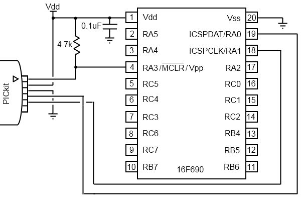
Below you can see a typical programming circuit.
The resistor between MCLR and Vdd is a pull-up resistor used to hold the pin high during operation. This is done because the active low MCLR (master clear) pin is used to reset the PIC. You can use a pushbutton to connect the MCLR pin to ground to manually reset the microcontroller.
Some PICs have an internal pullup on the MCLR pin and thus do no require the external resistor. The PIC16F690 is one of those so the 4.7k resistor can be omitted if you wish.
Some considerations need to be made if you want to use the ICSP pins in your application circuit. Series resistors should be used between ICSPDAT/PGD and the application circuit. The same applies for ICSPCLK/PGC. These are used to isolate the application circuit from the programmer. The application circuit must not interfere with the voltage levels and slew rate of the programmer data. If possible, dedicate these pins for ICSP.
It is possible to disable the MCLR input and use it as a general purpose IO pin, RA3. If you are using RA3, you must ensure that the application circuit is capable of handling the +12V Vpp from the programmer. One method to achieve this is to use a Schottky type diode or a resistor between the application circuit and the RA3/MCLR/Vpp pin. See the PICkit user guide for more information.
When working on a breadboard, it is useful to make a 6-wire programming cable by soldering six wires to male rectangular header. If you bought a clone PICkit, chances are you already have one.
The PIC16F690 can be oparated at any voltage from 2.0V to 5.5V. A bypass capacitor near Vdd is recommended to handle brief voltage fluctuations on the supply. The PICkit can also be used to power your circuit. However, this is limited to 100mA. If your circuit requires more current, you will want to use an external supply such as batteries or an AC adapter and a linear regulator (i.e. 7805).
One you have made all your programming connections, you are ready to start programming your PIC. We will start with digital I/O.